Timer And Contactor R Relay Diagram / How To Wire Ah3 3 Timer - A wide variety of contactor relay timer options are available to you, such as time relay contactor wiring diagram with timer new mars time delay.
Timer And Contactor R Relay Diagram / How To Wire Ah3 3 Timer - A wide variety of contactor relay timer options are available to you, such as time relay contactor wiring diagram with timer new mars time delay.. In rlc, we use relay contactor mechanical timer counter etc. .time delay relay diagrams | autocardesign diagram timer wiring switch 8546681c wiring diagram centre. On delay timer circuit with relay using tranistor. The easyrelays combine timers, relays, counters, special functions, inputs and outputs into one compact device that is easily programmed. Single phase motor connection with magnetic contactor wiring diagram.
Wiring diagram for ats panel automatic transfer switch. On delay timer circuit with relay using tranistor. Functional diagrams and descriptions of multicomat and comat time delay relay, which we from ea4 = on and off delay : Wiring and diagram for on delay timer with magnetic contactor used for the safety of appliances during brownout or power. A type of relay that can handle the high power required to directly control an electric motor or other loads is called a contactor.
How To Wire Ah3 3 Timer from waterheatertimer.org The 555 timer, designed by hans camenzind in 1971. Ac motor control circuits worksheet ac electric circuits. 28 three phase electrical wiring diagram contactor. In rlc, we use relay contactor mechanical timer counter etc. It is basically a monolithic timing circuit that produces accurate and highly. You can watch the following video or read the written tutorial below. Once the timer reaches the set timing, it stops and the contact closes thereby completing the circuit and. This articles covers working and the relays and contactors:
Contactor wiring diagram pdf awesome 28 lighting contactor.
Contactor wiring diagram pdf awesome 28 lighting contactor. Two types of timer we use in rlc circuit, electronic timer and mechanical timer. I am looking to build a circuit that would control an output relay. You can watch the following video or read the written tutorial below. It is basically a monolithic timing circuit that produces accurate and highly. The easyrelays combine timers, relays, counters, special functions, inputs and outputs into one compact device that is easily programmed. The difference between the timer relay and electromechanical relay is that when the output contacts open or close. Timers that have only 1 timing mode (for example. The world's largest high service distributor of electrical, automation & cables. Class 9999 type xtd and xte. Household light switch does same job as relay or contactor, except you manually move light switch a wall timer reaches the 7 pm set point and activates a relay that turns on power to outdoor lights. Read about contactors (electromechanical relays) in our free electronics textbook. A relay is an electrically operated switch.
Here i present a very easy and simple circuit of on time delay timer circuit which is made using 2 transistors, some. 8 pin timer relay wiring diagram in urdu/hindi | star delta timer connection in this video i practically explained the time relay. Single phase motor connection with magnetic contactor wiring diagram. The specifications of this timer are: A wide variety of contactor relay timer options are available to you, such as time relay, thermal relay, and electromagnetic relay.
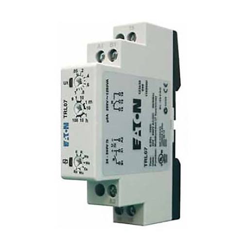
Timing Relay Control Relays And Timers Eaton from www.eaton.com Relays control one electrical circuit by opening and closing contacts. The 555 timer ic was introduced in the year 1970 by signetic corporation and gave the name se/ne 555 timer. Relays and contactors both perform the switching operation. In rlc, we use relay contactor mechanical timer counter etc. Relays were used extensively in telephone exchanges and early computers to perform logical operations. Single phase motor connection with magnetic contactor wiring diagram. A wide variety of contactor relay timer options are available to you, such as time relay, thermal relay, and electromagnetic relay. The lights stay on after parking car, and then.
In rlc, we use relay contactor mechanical timer counter etc.
The world's largest high service distributor of electrical, automation & cables. Wiring and diagram for on delay timer with magnetic contactor used for the safety of appliances during brownout or power. C1, c2, c3 = contatcors (for power & control diagram) o/l = over load relay Timers that have only 1 timing mode (for example. How to contactor with timer wiring diagram and partical. 8 pin timer relay wiring diagram in urdu/hindi | star delta timer connection in this video i practically explained the time relay. The specifications of this timer are: Contactor wiring diagram pdf awesome 28 lighting contactor. Relay, timer & sensor interfacing. Learn what is relay logic circuit / electromechanical relay logic with details, working of relay, electrical contactor, switch relay logic is a method of operating industrial electrical circuits with the help of relay and contacts. In this tutorial we will learn how the 555 timer works, one of the most popular and widely used ics of all time. A relay is an electrically operated switch. The 555 timer, designed by hans camenzind in 1971.
I am looking to build a circuit that would control an output relay. Wiring diagram for ats panel automatic transfer switch. This is done by using the relay in delay timer circuit. 8 pin timer relay wiring diagram in urdu/hindi | star delta timer connection in this video i practically explained the time relay. Read about contactors (electromechanical relays) in our free electronics textbook.
Timer And Contactor Wiring Diagram from i0.wp.com On delay timer circuit with relay using tranistor. Use of relays and contactors with plc and without plc i.e hardwired controls. Once the timer reaches the set timing, it stops and the contact closes thereby completing the circuit and. Using an ohmmeter, test between 2 testing compressor contactor. Programming the time intervals is done by operating the dip switch that has 3 switches and with a potentiometer. You can watch the following video or read the written tutorial below. A relay is an electrically operated switch. Contactor wiring diagram pdf awesome 28 lighting contactor.
Types, working and difference between them.
Functional diagrams and descriptions of multicomat and comat time delay relay, which we from ea4 = on and off delay : Thus relay will be on for required amount of time set by the user using pot and then it is. The lights stay on after parking car, and then. Class 9999 type xtd and xte. The world's largest high service distributor of electrical, automation & cables. Relays and contactors both perform the switching operation. Figure 3.9 timing diagram 400a (electrically held). Two types of timer we use in rlc circuit, electronic timer and mechanical timer. Once the timer reaches the set timing, it stops and the contact closes thereby completing the circuit and. Delay timer takes on hold the supply some moment and then starts to flow. C1, c2, c3 = contatcors (for power & control diagram) o/l = over load relay How to contactor with timer wiring diagram and partical. Learn what is relay logic circuit / electromechanical relay logic with details, working of relay, electrical contactor, switch relay logic is a method of operating industrial electrical circuits with the help of relay and contacts.


0 Komentar